> For the complete documentation index, see [llms.txt](https://docs.ceruleansonar.com/c/llms.txt). Markdown versions of documentation pages are available by appending `.md` to page URLs; this page is available as [Markdown](https://docs.ceruleansonar.com/c/tracker-650/getting-started/bluerov-ardusub-quick-start.md).

# BlueROV / ArduSub Quick Start

## You will Need:

<table data-view="cards"><thead><tr><th></th><th data-type="content-ref"></th><th data-hidden data-card-cover data-type="image">Cover image</th></tr></thead><tbody><tr><td>Tracker 650</td><td><a href="https://ceruleansonar.com/product/tracker-650-cmp/">https://ceruleansonar.com/product/tracker-650-cmp/</a></td><td><a href="/files/W0bKAaDH1w67TTSh38VJ">/files/W0bKAaDH1w67TTSh38VJ</a></td></tr><tr><td>DVL Mount</td><td><a href="https://ceruleansonar.com/product/tracket-650-bracket/">https://ceruleansonar.com/product/tracket-650-bracket/</a></td><td data-object-fit="contain"><a href="/files/8Atyn0x6YPlFD92OTSL8">/files/8Atyn0x6YPlFD92OTSL8</a></td></tr><tr><td>ArduSub Vehicle</td><td><a href="https://bluerobotics.com/store/rov/bluerov2/">https://bluerobotics.com/store/rov/bluerov2/</a></td><td data-object-fit="contain"><a href="/files/dU6zjw6rtSxsbiMBIrxT">/files/dU6zjw6rtSxsbiMBIrxT</a></td></tr><tr><td>Ethernet Switch</td><td><a href="https://bluerobotics.com/store/comm-control-power/tether-interface/ethswitch/">https://bluerobotics.com/store/comm-control-power/tether-interface/ethswitch/</a></td><td data-object-fit="contain"><a href="/files/OMpwuHhuuFdRGjZyp6BO">/files/OMpwuHhuuFdRGjZyp6BO</a></td></tr><tr><td>Computer with Network Connection to Vehicle</td><td></td><td><a href="https://images.unsplash.com/photo-1541807084-5c52b6b3adef?crop=entropy&#x26;cs=srgb&#x26;fm=jpg&#x26;ixid=M3wxOTcwMjR8MHwxfHNlYXJjaHw0fHxsYXB0b3B8ZW58MHx8fHwxNzgyMjM5MDAwfDA&#x26;ixlib=rb-4.1.0&#x26;q=85">https://images.unsplash.com/photo-1541807084-5c52b6b3adef?crop=entropy&#x26;cs=srgb&#x26;fm=jpg&#x26;ixid=M3wxOTcwMjR8MHwxfHNlYXJjaHw0fHxsYXB0b3B8ZW58MHx8fHwxNzgyMjM5MDAwfDA&#x26;ixlib=rb-4.1.0&#x26;q=85</a></td></tr></tbody></table>

## Hardware Setup

{% stepper %}
{% step %}

### Prepare Vehicle

Power off the vehicle completely and open the primary electronics enclosure
{% endstep %}

{% step %}

### Route Cable

Route the Tracker 650's cable into the vehicle's primary electronics enclosure.  Ensure the sealing surfaces and o-ring are lightly greased and free of debris. Tighten the cable penetration.&#x20;
{% endstep %}

{% step %}

### Connect Power

Connect the power leads to the vehicle's power distribution rails. (<mark style="color:red;">Red +</mark>, Black -)
{% endstep %}

{% step %}

### Connect Ethernet

Plug the 4 pin JST-GH connector into your vehicle's Ethernet switch.&#x20;
{% endstep %}

{% step %}

### Secure Cables

Secure wires using waxed lacing cord or zip ties with a small strain relief loop to prevent strain on the pins and connectors. Close the primary electronics enclosure.&#x20;
{% endstep %}

{% step %}

### Mount Tracker 650

Attach the Tracker 650 to the mounting bracket and mount the bracket to the vehicle

<figure><img src="/files/OlPUR0cza8YzVzJIJqJs" alt="" width="375"><figcaption></figcaption></figure>
{% endstep %}
{% endstepper %}

## Software Setup

{% stepper %}
{% step %}

### Install the Latest Version of SonarView

<https://ceruleansonar.com/sonarview/>
{% endstep %}

{% step %}

### Discover the Tracker 650

With everything powered on and connected, open SonarView and click **Device Discovery**. Ensure you see the Tracker 650 like so:

<figure><img src="/files/HXg4ja4YAA0SANbHC2N2" alt="" width="287"><figcaption></figcaption></figure>
{% endstep %}

{% step %}

### Configure Session

Return to the SonarView home page and click **Session Configurations**. In this page, you will need to create a vehicle for your mavlink2rest vehicle, a device for your Tracker650, and a session combining both.&#x20;

Below is a template file you can upload to Session Configurations. Make sure the tracker 650 and BlueROV details match your setup before continuing

{% file src="/files/8d2xYFvPqYFxa1wsoGF2" %}
{% endstep %}

{% step %}

### Discover Custom Session

Go back to the home page and click **Device Discovery**. You should see the custom session. Click **Connect**

<figure><img src="/files/xhRtKt2uO70Ios2FAM6Q" alt="" width="279"><figcaption></figcaption></figure>
{% endstep %}

{% step %}

### Check ArduPilot Parameters

In order for the Tracker 650 to send updates to the ArduPilot flight controller, certain parameters must be set. With the vehicle correctly configured in the session, powered on, and connected, click **Check Ardupilot Params** in the left drawer.

<figure><img src="/files/RA6iBN6dVlt7fW8my6ve" alt="" width="338"><figcaption></figcaption></figure>

This will check your vehicle's parameters and prompt you to change certain values if necessary
{% endstep %}

{% step %}

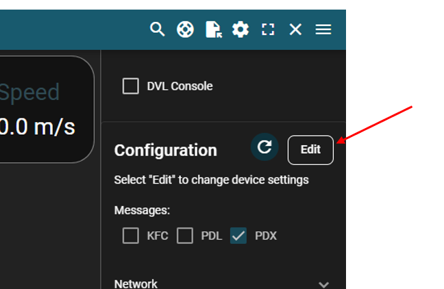
### Edit Device Configurations

In the right drawer click **Edit**

<figure><img src="/files/Gf5gplRKmIzprpmwRcV7" alt="" width="324"><figcaption></figcaption></figure>

Go to the dropdown labeled **Physical** and set the Yaw mounting angle. In the default configuration, the tracker is mounted with its arrow pointed 30 degrees to starboard from the direction of the vehicle as shown in the image below.

<div><figure><img src="/files/DmIgEZlqeRP0BTg19G4H" alt=""><figcaption></figcaption></figure> <figure><img src="/files/jk0H2W7fzgPG0W1LdBtR" alt="" width="375"><figcaption></figcaption></figure></div>

Go to the dropdown labeled **MAVLink** and ensure these values match your vehicle. These values are stored on the device itself, so you need to make sure they match what you set for your session:

<figure><img src="/files/R42VLNFqN4mF2Up9D2S9" alt=""><figcaption></figcaption></figure>

{% hint style="info" %}
**Send Distance:** Send distance measurements to the flight controller to make the Tracker 650 also act as an altimeter

**Auto Origin:** On boot, have the tracker firmware send an origin of 0,0 so dead reckoning works without a global reference
{% endhint %}

Once you're satisfied, click the green send icon to update the device's internal configuration:&#x20;

<figure><img src="/files/JY4VHrOiNqcbVLXxq4K3" alt=""><figcaption></figcaption></figure>
{% endstep %}

{% step %}

### Confirm Functionality

Open the web UI for your mavlink2rest server (by default at <http://192.168.2.2:6040/>). Here you can confirm that the Tracker650 is sending VISION\_POSITION\_DELTA messages to your vehicle's flight controller:

<figure><img src="/files/VpFrkojGM7hPJmUuxa11" alt=""><figcaption></figcaption></figure>
{% endstep %}

{% step %}

### Send Global Origin (Optional)

In order for ArduSub to do dead reckoning with the Tracker 650, it must start with a global origin. A simple way to do that is to return to the main view and click **pick location** in the left drawer. This will open a dialog that allows you to send coordinates to the vehicle for where it should start from. If you have a GPS configured, this step is unnecessary&#x20;

<figure><img src="/files/f8yNIRNWH5GWttySz80W" alt=""><figcaption></figcaption></figure>
{% endstep %}
{% endstepper %}

With these steps completed, ArduSub should now be able to do position hold, dead reckoning, and waypoint navigation

## Next Steps

<table data-view="cards"><thead><tr><th data-type="content-ref"></th><th data-hidden data-card-cover data-type="image">Cover image</th></tr></thead><tbody><tr><td><a href="/pages/vtMbCeXgBTNJHovfM0DW">/pages/vtMbCeXgBTNJHovfM0DW</a></td><td data-object-fit="contain"><a href="/files/3vNdpPSajCpmAXkXiRL5">/files/3vNdpPSajCpmAXkXiRL5</a></td></tr><tr><td><a href="/pages/DC8aQstTT1fbXtqKA3yV">/pages/DC8aQstTT1fbXtqKA3yV</a></td><td><a href="/files/HY0be4WtbmrJc3FMB7Ks">/files/HY0be4WtbmrJc3FMB7Ks</a></td></tr><tr><td><a href="/pages/4S144aKwJWDLNow2I71e">/pages/4S144aKwJWDLNow2I71e</a></td><td data-object-fit="contain"><a href="/files/Z4RMe9MOKOLviXL8SGpK">/files/Z4RMe9MOKOLviXL8SGpK</a></td></tr></tbody></table>