📖
Cerulean Sonar Docs
Docs DirectoryStore
Ethernet ROV Locator
  • ROV Locator
  • Overview
  • General Specifications
  • Quick Start for BlueROV
  • Fundamentals Useful to System Designers
    • Sound Reflection and Absorption
    • Multipath
    • Ping Length
    • What to Do About Multipath and Other Issues
    • Clock Drift Expectations
    • Accuracy Expectations
      • Accuracy Test: Topside GPS
      • Accuracy Test: 110 Meter Slant Range
      • Accuracy Test: 295 Meter Slant Range
    • Operation in a Pool
  • Configuring the ROVLe
    • Finding the Configuration Web Page
    • Example Configuration Web Page
    • Live Status Page
    • Setting Device Type
    • Setting the Static IP Address
    • Setting the Fallback IP Address
    • Setting the MAVLink REST Server Parameters
    • Setting the Secondary (GNSS) MAVLink Interface
    • GPS/GNSS Forwarding (Re-tweeting)
    • Magnetic Declination
    • CIMU Calibration Offsets
    • Speed of Sound
    • GNSS Antenna Mounting Rotation
    • Output Messages
    • Configure Simulation
  • System Variants
  • Autosync
    • Autosync Mission Scenarios and Mission Suitability
    • Autosync Availability
    • Autosync GPS/GNSS Output
    • ROVL Channels (Autosync only; Operating Multiple Units in Proximity)
  • Communicating With the ROVL
    • Serial Parameters
    • The Ethernet Interface
      • Tips on How to Find the IP Address Assigned to Your Ethernet Adapter
      • Blue Robotics Discovery Protocol (Ethernet Only)
    • Packet Format
    • Messages from ROVL to Host
      • $USRTH Receiver-Transmitter Relative Angles Message
      • $USTLC Target Location Message
      • $USINF/$USTXT Information Message
      • $USERR Error Message
      • $USNVM Non-Volatile Memory Message
    • Messages from Host to ROVL
      • NMEA-Format Messages to Receiver
      • Valid Commands from Host to ROVL, Serial and Ethernet
      • Valid Commands from Host to ROVL, Ethernet Only
        • Command: DHCP
        • Command: FALLBACK-ADDRESS
        • Command: IP-ADDRESS
        • Command: HOST-ADDRESS
        • Command: MAVLINK-ADDRESS
        • Command: MAVLINK-AUTO-ORIGIN
        • Command: MAVLINK-SYSID
        • Command: PAUSE
        • Command: RESUME
        • Command: RETWEET-GPS
        • Command: RETWEET-GPS-ADDRESS
        • Command: RETWEET-message
        • Command: SEND-ROV-POS-TO-MAP
        • Command: SEND-TOPSIDE-TO-MAP
        • Command: SEND-USRTH
        • Command: SEND-USTLC
        • Command: UNICAST-TO-ME
  • Cerulean Inertial Measurement Unit (CIMU)
    • CIMU Calibration Background
      • CIMU Magnetometer Calibration
      • CIMU Accelerometer Calibration
      • CIMU Gyro Calibration
  • Operating and Accuracy Considerations
  • Multi-Unit Operation (Swarms)
    • Multi-Unit 1:1
    • Multi-Unit 1:2
    • Multi-Unit 2x1:1
  • ROVL Mounting
    • ROV/Deepside Mounting
    • Topside Mounting
    • Simple Topside Deployment Fixture
  • ROVL Wiring
    • Standard Cabling Options
    • ROVL-e PC Board Internal Connections
      • JST-GH Connector Pin 1 Identification
      • Ethernet/Power Connections
      • Serial Connection
      • USB Connection
      • GNSS Compass Main (4-pin) RS-232 Connection
      • GNSS Compass RTK (2-pin) RS-422 Connection
    • Electrical Noise
  • Connecting and Powering Your ROVLe Ethernet Receiver or Transceiver
    • Example Power Injectors
    • Data Connection
    • Example Power/Wi-Fi Setup for Remote Usage
    • Battery
  • Mounting Dimensions
    • Mk II Receiver with Omnitrack Top
    • Transmitter/Transceiver/Receiver with Standard Top
    • Mk III Transcceiver
    • ROVLe Omnitrack Top
    • ROVLe Standard Top
    • Example Mounting Scheme with 3D-Printed Bracket
  • ROVL Coordinate Systems and Angles
    • Definitions
    • NED or "Compass" vs. ENU or "Math" Angles
    • Math to Compass Frame Conversions
    • Transducer Down Orientation
    • Transducer Up Orientation
    • Receiver/Transceiver Orientation Frames
    • Best Operating Envelope
  • Appendix: Math for Computing Remote Latitude/Longitude
    • Receiver & GPS at Topside and Transmitter Deepside
    • Transmitter & GPS Topside and Receiver Deepside
  • Appendix: Factory Usage Command Set
  • Troubleshooting
    • How to Tell if Your Mk II Receiver is Working
    • How to tell if your Mk II Transmitter is working
    • What to do when you find an unresolvable problem when troubleshooting
  • Copyright
Powered by GitBook
On this page
  1. Troubleshooting

How to tell if your Mk II Transmitter is working

This discussion is valid for a Mk II Transmitter. This should be the second step if you are troubleshooting a system.

PreviousHow to Tell if Your Mk II Receiver is WorkingNextWhat to do when you find an unresolvable problem when troubleshooting

Last updated 1 month ago

To determine if the transmitter is working:

  1. Be sure power is connected. The ROVL Mk II transmitter will work with just power and ground supplied. See here for permitted power configurations.

  2. Take the transmitter to a place where it can "see" the sky (and is not submerged) and wait for it to achieve GPS lock (typically 30 to 60 seconds). When it does, it should start "clicking" at a 1 Hz rate. Even if you cannot hear the clicking, you should should be able to feel it click when you put your hand on the sensor cone. The transmitter should continue to click even after it loses GPS lock by submerging or being taken into a building.

  3. Normally, this is all that is required to check operation of the transmitter, unless you have changed the factory settings.

To review or change the factory settings:

  1. To look at the factory settings, you must be able to talk to the transmitter over its serial link.

  2. The supplied transmitter cable has TTL serial connections (the green and yellow wires). See here for drawings. BE SURE OF YOUR WIRING. the TTL connections are suitable for connection to a TTL serial port such as is found on a Raspberry Pi or Arduino. An adapter is needed to talk to a PC USB port. BE SURE THE ADAPTER IS NOT USB TO RS-232. RS-232 signal levels will fry your transmitter's brain.

  3. Alternatively: Assuming you have already established a connection between the Receiver and your PC, you can carefully remove the mounting interfaces from both your Receiver and Transmitter, and temporarily move the Receiver cable to the Transmitter instead of using the Transmitter's cable. NOTE: the connectors are delicate and almost no force is needed to mate and un-mate it you have correctly actuated the connector lock. Pulling hard will rip out the wires from the connector if you are lucky, or rip out the board-mounted connector from the PCB if you are unlucky.

  4. Once you have connected whichever cable you are using to a device that has a terminal emulator, you can proceed. NOTE: you can use CeruleanTracker as a terminal emulator. Note the "Utility Terminal" button at the bottom of the dashboard tab of the main screen.
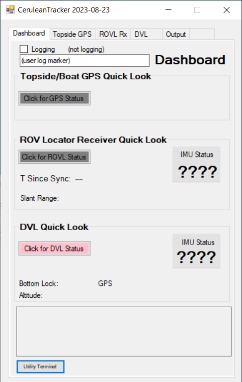
  5. Be sure the COM port you want to use is not already grabbed by another application or by another device in CeruleanTracker. Be particularly sure the ROVL Rx tab has not grabbed the com port if you are using the Receiver's cable.

  6. Be sure you have the the terminal emulator to 9600 baud. The Mk II Autosync transmitter emulates a serial GPS and thus connects at 9600 baud.

  7. You should see something like this, with messages continuously scrolling:
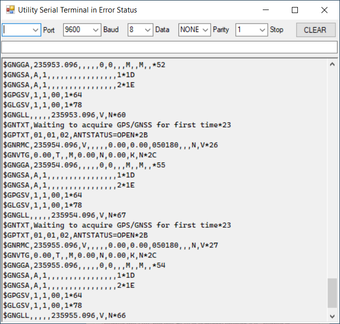
  8. What you are seeing is the GPS emulation. In this case the GPS does not have a satellite lock. If it did the messages would be similar but longer.

  9. If you do not see messages scrolling, look below at step 14.

  10. To see the configuration, send it a '?' (question mark) followed by Enter. A menu and configuration will appear and immediate scroll out of sight. What you will need to do is send '?', wait about 1 second for the configuration, then unplug the USB cable to the transmitter. Then scroll the window back until you see something like this:
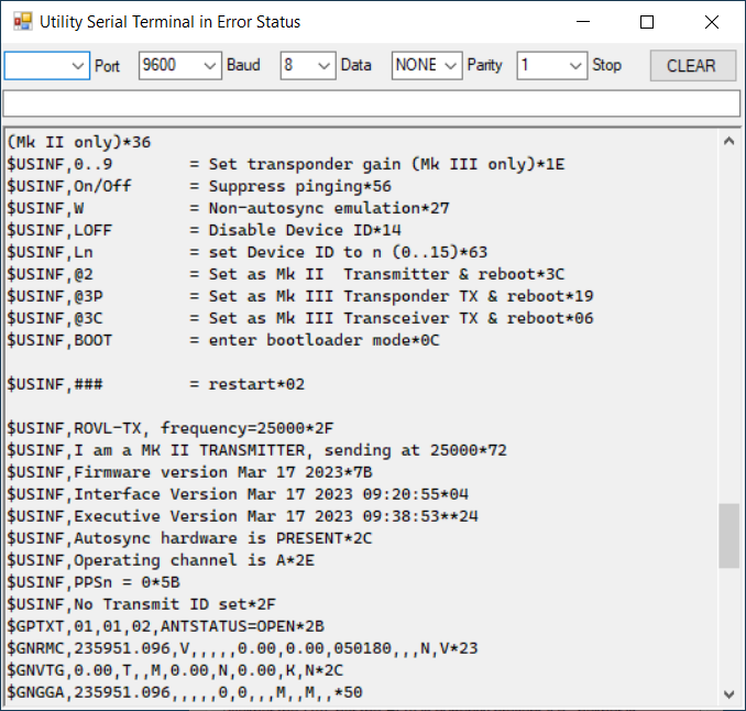
  11. It should say "Operating channel is A". If it says something other than "A", unplug, re-plug, send it an 'IA' command (without the quotes, followed by Enter). Unplug, re-plug, and repeat from step 4 to ensure it is switched to channel A.

  12. It should say "No Transmit ID set". If it lists a transmit ID, unplug, re-plug, send it a 'LOFF' command (without the quotes, followed by Enter). Unplug, re-plug, and repeat from step 4 to ensure it is set to no transmit ID.

  13. Go back up to the first step 1.

  14. If there was not a scrolling display of GPS messages in step 7, but there was gibberish or a blank screen: Try switching the baud rate to 115200.

  15. Send it a '?' (question mark) followed by Enter. Repeat this a couple of times. You may see something like this:
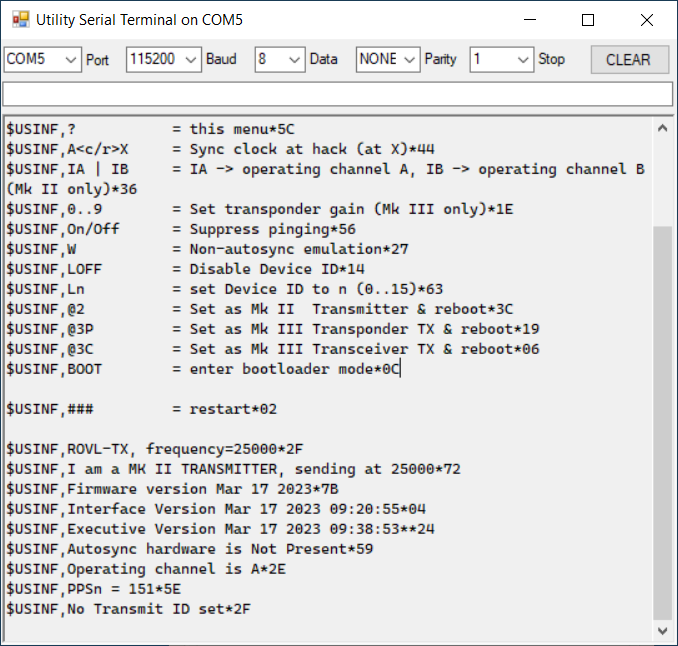
  16. If you see "I am a MK II TRANSMITTER, sending at 25000" and you see "Autosync hardware is Not Present", then you either have a bad GPS board (contact us) or you have an old Mk II non-autosync transmitter (quite rare).

  17. If you see "I am a MK III TRANSPONDER TX, sending at 25000", send it a '@2' command (without the quotes, followed by Enter). After it reboots, the baud rate will change to 9600 baud, so change the baud rate on the terminal emulator and go to step 4.

wiring
Dashboard tab of main CeruleanTracker window